Testing of components
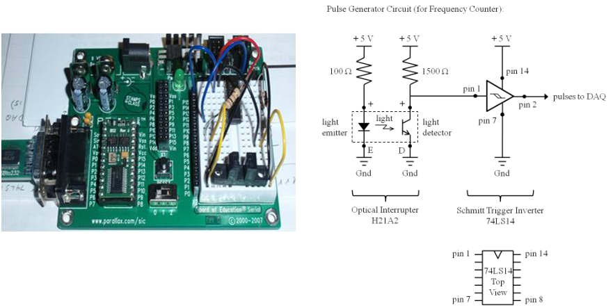
The photo interrupter sensor was tested using the apparatus shown below. The photo interrupter was mounted to a PIC board and connected to a micro-controller via a noise suppressing Schmitt trigger circuit (shown below). A program was written in BASIC to continually read counts and translate to count rate. The Dremel was operated over full frequency range and measurements were taken using the apparatus. The test results verified that no deviation existed between the expected and measured Dremel frequencies.
System Testing
After the apparatus was installed in the icing wind tunnel the system was tested and adjustments were made.
Test Procedure for Use of Apparatus
•Samples for ice accumulation testing must be prepared and fixed onto SEM mounts.
•SEM mounts are attached to holder at base of push rod and angle set.
•Close test chamber.
•Turn on fan.
•Connect liquid nitrogen tank to radiator inside tunnel.
•Set wind speed and temperature in tunnel.
•Set Dremel speed. •Turn on water to nozzle.
•System operates for desired time period.
•Weigh samples in tunnel and compare data.
